|
This information is provided as guidance Only. Use this information at your own risk! This site is not affiliated with General Motors or Cadillac. All trademarks are property of their respective owners. |
 |
|
This information is provided as guidance Only. Use this information at your own risk! This site is not affiliated with General Motors or Cadillac. All trademarks are property of their respective owners. |
|
Navigation Install Phase II: (for non Nav CTSs)How to add Voice commands and Audible directionsExplanation: After installation of a Factory Navigation Radio into a non-Navigation equipped CTS, Part II describes the fabrication of the wire harnessing to get the audible directions and voice commands working like the factory installed systems. Non-nav CTSs are missing this wire harnessing from the factory. This works with the Bose amplifier only, since the base amp does not have provisions for audible directions. The voice commands should work, as the On-Star (VCIM) is identical and only missing the harness. Disclaimer: Mod at your own risk - double check the schematics when you install the terminals. It’s also a good idea to check continuity of each wire after the terminals are crimped prior to installing them into connectors. I will not accept responsibility for errors or omissions, or incorrectly installed wiring. Miscreant did detailed instructions for installing a factory navigation system in a non-nav CTS. He sold his before finishing his write-up on installing the wire harnessing for voice commands and audible directions. After a year or so of studying schematics, searching for terminal part numbers, vendors, and availability, I finally built a prototype harness and installed it in my CTS while I had the trunk taken apart to install V shocks and Eibach lowering springs. So for those so inclined, I’ve documented part numbers, vendors, pricing, and the install here. Schematics for these harnesses are at http://www.cadillacfaq.com/faq/answers/pdf/nav.pdf . Parts Needed: The hardest part is locating parts. We need three types of terminals and one connector. I’ve also included the parts for the VSS terminal, so one doesn’t have to buy a reverse VW harness (VW01R) for $10 and pilfer a single terminal. Here’s a list of what you need:
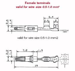
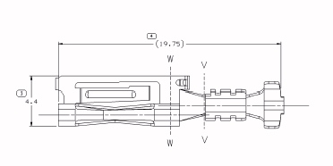
Note many of these parts have minimum quantities. (1) PowerandSignal have a minimum purchase of $25, and only sell in a strip of 200. I had to buy 400 terminals, even though I only needed two. Needless to say, I have a lot of terminals and connectors (I purchased 20 sets), etc., left over that I’m willing to send to those interested in building a set of harnesses. You’ll need to locate your own Nav C1 terminals from your dealer, though. I only ask that you donate $10 to each www.CadillacFAQ.com and www.CadillacForums.com (or become a supporting member) to help Reed and Sal keep these valuable sites up and running. They’re a wealth of information. Without which, I would not have been able to get this harnessing done (as well as a hundred other mods). Framatome DCS-2 terminals for the Nav C1 connector are almost non-existent and difficult to find. I took a sample (you can print the first picture below and bring it in) to my dealer and he found some in his terminal repair kit. He sold me five terminals for $0.60 each. This would be much easier than finding a vendor. The repair kit was from SPX and the terminals were ZL-Term 4-969005-1. He told me to call 1-800-GMTOOLS if I needed more.
Cut two 16’ lengths from your Belden twisted shielded pair roll of wire. I used a little over 15’ lengths, but felt it was barely long enough for good flex at the Nav. A little extra will let you tuck it in wherever you want, allowing for a little variance in the routing. From each end of both cables trim about 1.5” of the black outer insulation back. Also trim the silver mylar shield back, being careful not to cut the red or black wires or the single drain wire. Strip about 0.25” of insulation from each of the black and red wires. Now we’re ready to crimp terminals on the ends. This will not be clean without the proper crimp tools, but since we’re hacking this, just be very careful to get the best crimp possible making sure the wire does not pull out with a slight yank. Connector Pinouts:The first wire harness is for the voice commands. Normally, on every CTS, the microphone sends voice signals to the VCIM. What we need is those signals to travel back to the Nav. This is accomplished via a C3 connector on the VCIM, which is missing the harnessing, and a few missing terminals on the existing Nav C1 connector. On one end of the first harness, we want to crimp a VCIM terminal on each of the red, black, and bare wires (3 total). On the other end, we need to crimp a Nav terminal on the red and black wires (2 total) and clip the bare drain wire flush with the black jacketing so it’s not hanging loose. As in all shielded data wiring, the drain wire is only to be connected to a ground on the transmitting end (the VCIM in this case). Once this is done and you’re satisfied with the crimps with no bent terminals, we need to populate the new black VCIM C3 connector (Newark PN: 50H8378). We will put the red wire in position 2, the black in position 4 and the drain wire in position 5. Here is a drawing of the connector looking at it from the end (the terminals will come in from the back). Note: we have a red and black wire substituting the factory pink and pink w/black stripe (red = pink, black = pink w/black stripe) . . . we’ll need to remember this when we connect the Nav end of the harness, using the schematics. 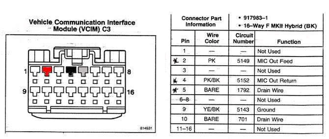
The second harness is to enable audible directions from the Nav to the Bose amplifier. This is accomplished by connecting a few missing terminals from the existing Nav C1 connector and the existing Bose C3 connector. Crimp a Nav terminal (3 total) on each of the red, black, and bare drain wire on one end of the second 16’ section of wire. On the other end, crimp a Bose terminals on each of the black and red wires (2 total), cutting the bare drain wire on this end back to the black jacketing, as we did on the first harness. If you want to build a VSS harness from Phase I, you need about 30” of brown 22 gauge wire, a wire tap, and one of the (PN:93B2944) Nav C2 terminals. This goes in position 7 of the C2 connector, as shown in phase I. Total cost is $0.23, rather than $10 for a reverse VW harness. The Install:First, we need to remove the rear seat bottom (pull straight up on the front, then pull forward to remove). Then four nuts on the bottom of the rear seat back which are now exposed, then four nuts from the trunk holding the top of the seat back. The seat back then can be pulled toward the front of the car. Be careful to pull it from under the seat belts, especially the middle one. This can be awkward, so having a friend help will keep paint scratches in the door jam to a minimum. From the trunk, unscrew the spare tire hold-down so the cover can be lifted (no need to remove it entirely). Unscrew the large (2”) buttons holding the trunk covers in place. First the one between the tail lights comes out, then each side panel. This will expose the VCIM on the passenger side, and the Bose amp on the drivers side. This is critical to properly routing the wire harnesses to the front of the car following the factory routing, as much as possible. 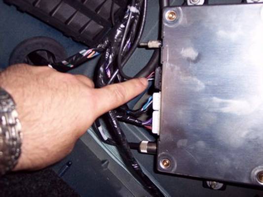
For the VCIM, plug the new harness with the black connector into the missing C3 slot (the uppermost one), as shown in the picture above.The push tab on the connector will face the outside of the car. Then zip-tie it in place along the factory harnessing going forward next to the rear shock and into the rear seat area. 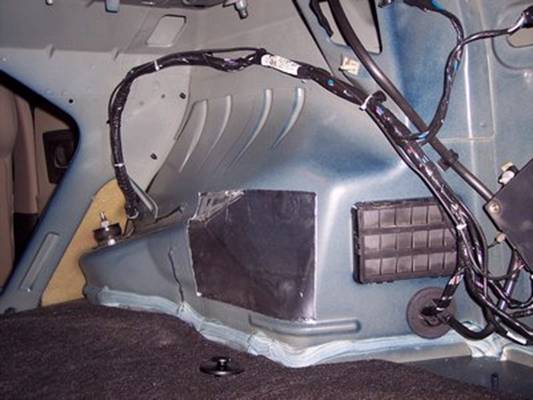
Now get out of the trunk and go inside the passenger space. Tuck the wire under the door molding until you get to the front seat kick panel.Tuck it under the kick panel so it exits at the top.Remove the passenger side courtesy light ‘tray’, being careful not to touch the lamp . . . it’s This panel is held in place by two Phillips head screws nearest the seat, and two 7mm head screws at the forward edge.Once these are removed, there are two push clips on the rear-most (closest to the seat) edge that you gently push forward to unclip them, and to let the panel drop down. 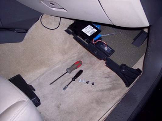
Run the wire harnessing above this area under the dash, and feed it into the center stack next to the ash tray.Put the tray back up, fitting the forward edges onto guide pins, then rotate up to engage the two push clips.Reinstall the two 7mm screws and the two Phillips head screws to secure it.Now run in the house and get an ice cube, since you surely touched the hot courtesy lamp and got a second degree burn on your finger tips. If you didn’t, you’re one up on me. For the Bose harness, unscrew the three nuts holding the Bose amp in place.I think it’s an 8mm deep-well socket, but since I didn’t have one, I used a wrench to break them loose and then unscrew them with my fingers. Look for a small 6 pin connector with a red edge locking tab on the backside of the amp. Depress the locking clip and unplug it from the amp. Pull the red locking tab out (it’s held in place by a push tab), being careful not to let the existing 3 wires out. 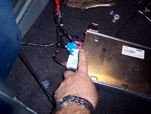
The Bose C3 connector terminals are wired 5-10, even though there are only six holes, with the first being empty.The last two positions are open, and these are numbered 9 and 10.Plug the Bose terminals from your harness into the last two holes, the red one in position 10, and the black one in position 9, taking note on the direction of the polarizing tab on each of the terminals.They only go in one way. Like the VCIM harness the factory uses different colors than we are using. Our Red = factory Yellow, and our Black = factory White. Since they’re not installed on our car, it really doesn’t matter what the factory did, other than to follow the factory schematics. Reinstall the red locking tab and plug the connector back into the Bose amp.Here is the view of where the terminals go, viewing from the end of the connector. The terminals will install from the back. 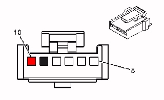
Re-mount the amp using the three nuts. Zip-tie the new harness along the factory harness, following a similar path as the VCIM harness, but on the side. 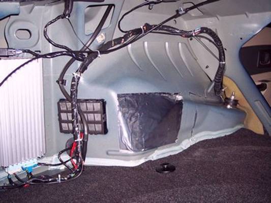
Tuck it under the door molding up to the front kick panel having it exit at the top of that. The panel under the steering wheel is held with three Phillips head screws. Just like we did on the passenger side, remove those screws, allowing the panel to drop a few inches. Tuck the harnessing up and push the ends into the sides of the center stack near the ash tray. Reinstall the three Phillips head screws holding the panel in place. From Phase I, remove the upper AC vents with a putty knife being careful to apply gentle pressure and not chip or crack the vent. Work your way around until it pops out. Next, open the ashtray and remove the single bolt holding it in place via a small hole behind the ashtray.Then using a putty knife, gently the edges of the ashtray/climate control unit, and tuck it aside. Remove the four bolts holding the NAV in place and disconnect the and antenna connectors, and the C1, C2 and C3 connectors. Set the Nav aside. From where the ashtray was, pull the ends of the wire harnesses from where we tucked them in, and feed them up the back of the center stack so they exit near the factory harness. Here’s the fun part.Make sure you install the terminals into C1 so the slot parts face sideways (-) not up and down. Look down the front end of the connector with a flashlight to see how the others are aligned. The terminals will install either way, but the connector won’t clip in place on the NAv if these are not correct. For the VCIM harness, we want to install the red wire in position 6, and the black wire in position 9.For the Bose harness, we want to install the red wire in position 4, the black wire in position 16, and the drain terminal in position 2. They should click into place easily, and be flush with the connector. Zip-tie the wire harnesses to the factory harness to keep them out of the way. 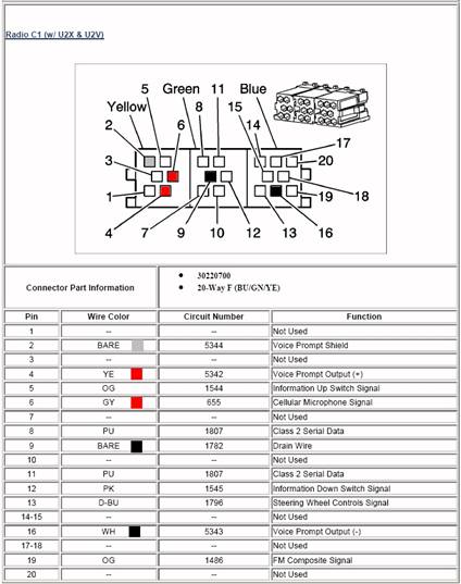
Above shows the placement of the terminals in the nav C1 connector.Below is the Nav C1 connector viewed from the backside. It will be a mirror image of the above drawing, which is the view from the front of the connector. 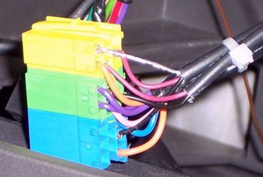
Follow the instructions for “Installing the Navigation Radio” from Phase I, or to repeat: Holding the nav back in place near the center stack, reinstall C1, C2 and C3, the and the antenna connectors. Reinstall the Nav making sure that it fits flush with the center stack before bolting the four screws back in. Snap the ashtray/climate control panel and the AC vent panel in place. You don’t need to reinstall the single screw holding the ashtray in place. Now before you rush off in celebration, you have to enable the voice commands in the nav. While Nav is selected, hit the large knob on the right to bring up the nav menu. Make sure ‘Guidance’ is enabled and scroll down to ‘Volume’. Adjust it somewhere in the middle or you’ll be blown out with a female voice yelling directions at you (while you’re wife isn’t even in the car!). My girlfriend thought it was weird, because when you turn the knob to the right the female voice says “Louder”, and when you go the other way, she says “Softer”. Do that a few times with a woman in the car and she’ll think you’re a sick-o. Now take the car for a spin, selecting a destination first. It will be very cool at first, Then you’ll probably get sick of it and turn the audible directions OFF after a few days. But at least the install is like the GM meant it to be! Install Time: Approx. 2 hours (mostly to remove/reinstall
the rear seat and trunk panels | |||||||||||||||||||||||||||||||||||||||||||||||||||||||||||||||||||||||||