How do I install a Radar Detector (specifically a V1)?
In this instance I will assume that you using a V1. V1 = Valentine 1. www.valentine1.com
A little background on V1, Mike Valentine originally designed one of the very first escort radar detectors and has since left the company and started his own product line, his products are generally considered the best available on the market however they come from heavy price tag. Beware you can only by a Valentine 1 from the Valentine 1 web site there are no deals to be found anywhere. I have run my V1 in parallel with a K-40 (professionally installed) on one occasion and on another against a Bell something or other, nothing compares to the V1 – in my opinion. It’s pricey but well worth the price. Some users note that they get a lot more false alarms using the V1, but that’s because it’s significantly more sensitive than anything they have used before. But hey the V1 is the only detector I know of that’s programmable, if it’s picking up every set of K-mart doors you can turn down the sensitivity!
For those of you who do not yet have a V1, it will come with two styles of mounting: a belt holster like clip that’s used for visor mounting and traditional suction cup mounts. For power it uses standard RJ-11 telephone line cord. This is the wire that runs from your home telephone to the wall jack. It is relatively flat and has four conductors; I believe some is supplied in the V1 box. Worst case you go to your local hardware store or radio shop and buying the smallest length of telephone cord you can find 3 or 6 feet (black colored cable is preferred). If you have a three foot cord with male connectors on both ends, simply cut that cable in half. You’ll only need one piece, the other is just there are as a backup.
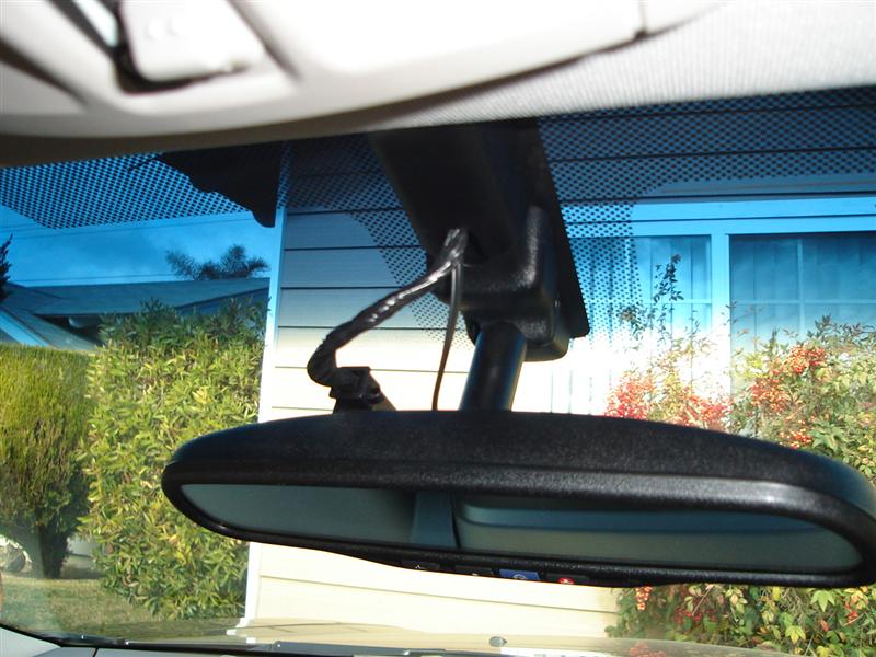
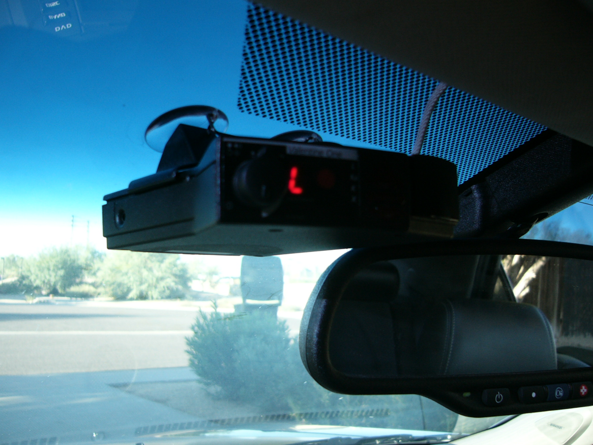
I installed on my V1 into my CTSV without the remote display unit available, I do have that in another vehicle. My V1 is suctioned cupped to the windshield directly above and beside the inside rearview mirror. My instructions cover mounting the radar detector in this location. To begin the installation process first make sure that he vehicle has been off - not even a key in the ignition for at least 30 minutes (I’ll explain why later). It is preferable that you do this outside in the sunlight as opposed to indoors in a shop environment or any other place without bright lighting. You will need a wire stripper, crimper tool, some connectors (some should be included in the V1 installation kit), and a 12 V test light.
Adendum/Alternative install (added 4-07)
I installed my Bel RX65 yesterday and didn't want the Delayed +12V connector as described in your article because should you park in a lot with annoying interference radar the detector would continue to sound for 10-20 mins after exiting. Therefore I hunted for a true +12V accessory wire that turned off imediately and was easily accesible.
The solution is the Pink wire (4th wire down, bottom row) in the Rearview mirror wiring harness (It is the +12V for the auto dimming mirror). There is a black wire with white strip that functions as the ground as well. I had to take the harness out of the mirror and test it, but now that I have identified the wires, just remove the black cover in the center of the window where the wires come through by carefully spliting the black electrical tape covering on the wires going to the mirror and tap into the Pink (+12V) and black with white strip as the ground and that's it.
A TRUE +12v accsesory connection, no delay turning off, and no need to tug and pull the overhead console with dimmer/sunroof control and short microphone cord off the headliner!!
Normal install
Phase 1 Remove the overhead console, as follows – (3 mins.)
1. Remove the Dimmer knob (would you call this a knob?) by pulling straight down on it (gently yet forcefully), or get your nails under the head of it. It will snap right out.
2. If you have a sunroof - Removing the Control knob is NOT necessary.
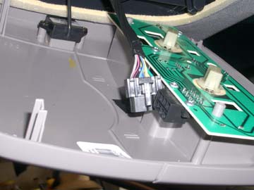
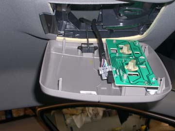
All you need to do is pull on the back of the panel (the panel that has the knob, overhead lights, and microphone) and then the front to pop the clips out. Be careful, on my V the wire to the microphone is VERY SHORT and will not unplug. Once this is done, you can look from the passenger side and you will see two connectors. One is for the sunroof switch. The other, the one you need, is the lighting harness. Unplug the lighting harness and make your connections here.
3. Once these items are removed grab at the back/rear of the console and once again pull down (you will hear some plasticy snapping noises - these are the clips - usually not breaking just giving as expected). I don't recall if the front is also clipped in or just wedged in under a lip.
4. Remove electrical connections (if necessary) or just let the thing hang, we did not need to remove it for the 10 minutes we had it down.
Phase 2 – Wiring (5 mins.)
You should have at least 1 approximately 18 inch long piece of telephone cable with one bare/cut end, the other end should have an RJ-11 MALE telephone type connector on it.
1. (This and the next step are the most difficult part of this operation) Carefully pry a small (width) the area of the headliner away from the mounting near the windshield.
2. Then feed the bare end of the cable from the windshield under the headliner to the opening where the overhead console normally appears.
3. You may wish to (roughly) place the V1 in it’s final mounting place, on your windshield, and if need be, trim back the bare end of this cable – I left most of my extra cable tucked up (and hidden) in the headliner, so that in case I need/want to move the detector to a different (yet still reasonably close) location, it would be easy. I first had mine on the passenger side of the inside rear view mirror, the decided to move it to the driver’s side.
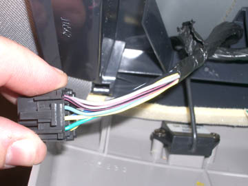
4. With the exposed end of the cable now in the hole of the headliner, trim back about two to three inches of outside insulation, exposing 4 insulated wires.
5. At this point if you’re not using the remote display unit (and this install assumes that), you can cut the yellow and black wires off completely they are not used a stand-alone installation.
6. Blue wire with WHITE stripe (adjacent to the black wire in the connector - if we call the black wire position 2 in that row (there are 4 wires) then the blue/WHITE stripe wire is position 3) = +12V delay switched. (see below)
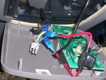
7. Use wire clips to attach to one of the seeming to be ignition hot wires and another to a ground.
8. Strip about three-quarters of an inch of insulation off both the red and green wires and crimp the appropriate blade type connectors onto them (I can supply pic of these connectors if need be).
9. Insert the 2 bladed connectors into the 2 wire clips.
10. Plug in your V1 and turn it on. If it fails to power up (and make the soon to be all familiar self test sounds), swap (reverse) the connections that you plugged into the wire clips in Step 9. You will NOT do any harm to the V1 if the power to it is reversed, it just won’t power up.
Phase 3 – Tidy up (2 mins.)
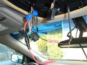
1. Tuck the wires and wire harness back into place, pull extra telephone wire up and out of the way.
2. Reinstall the overhead console by CAREFULLY smacking the console (with properly aligned pins to holes) back into place. We had to smack it pretty hard (at each clip).
3. Clip the knobs back into place.
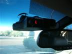
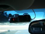
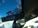
4. Mount your V1 in desired location, tuck cable behind review mirror.
You can also tuck the wire behind the black plastic that protects the wires leading to the rear view mirror. The black plastic piece is easily removed. See pictures below.
*The ignition hots didn’t turn off with the ignition, WHY? Well our lovely CTS has “DIH”, Delayed Ignition Hot. These stay active for 10 or 20 minutes after you turn off the car, then the car computer shuts down all the power (there is something about it in the manual with a name that GM Marketing came up with). In my case, during the day my V1 only powers up when the ignition is turned on (and will stay on for a bit after the car is turned off – so if you jump out to get fuel it will stay on, but by the end of lunch it’s off). At night my V1 powers up when I hit the key fob to open the doors and again shuts off after 10 or 20 minutes after shutting down the car.
THANKS BEN!!
UPDATE:
And now for the all important wire color codes CONFIRMED on the sunroof version:
Black = ground
Blue wire with WHITE stripe (adjacent to the black wire in the connector - if we call the black wire position 2 in that row (there are 4 wires) then the blue/white stripe wire is position 3) = +12V delay switched.
Thanks WILDWHL
Here are some images of my install:
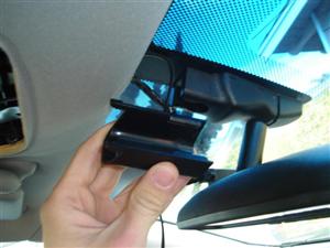

Installed Pictures
Thanks DGTAL
This site is not affiliated with General Motors or Cadillac. All trademarks are property of their respective owners.
All pages copyright www.cadillacfaq.com.
Donate to keep this site live and ad free Here
Main Page---
List Style FAQ---
Document Library---
Image Library---
Video Library---
Vendor/Mod List---
DealerRank---
V Newsletter---
Other Links
For questions or comments email ctsvett@earthlink.net